Wishlist
The products are limited
The products are limited
In our previous article, we began analyzing the perplexing phenomenon of single-row roller disengagement in two spherical roller bearings within a gearbox shaft system. We noted that when a spherical roller bearing experiences a certain magnitude of axial load, the rollers on the side not directly bearing the axial load can exhibit a "disengaged" state.
Since this "disengagement" is detrimental to bearing operation, it strongly suggests that the spherical roller bearings are not designed to withstand such large axial loads in this particular setup. For this specific case, our primary goal is to identify the source of this significant axial load on the bearings, evaluate its reasonableness within the design, and then, based on our conclusions, pinpoint the root cause of the problem and implement a solution. This article will focus on that analysis process.
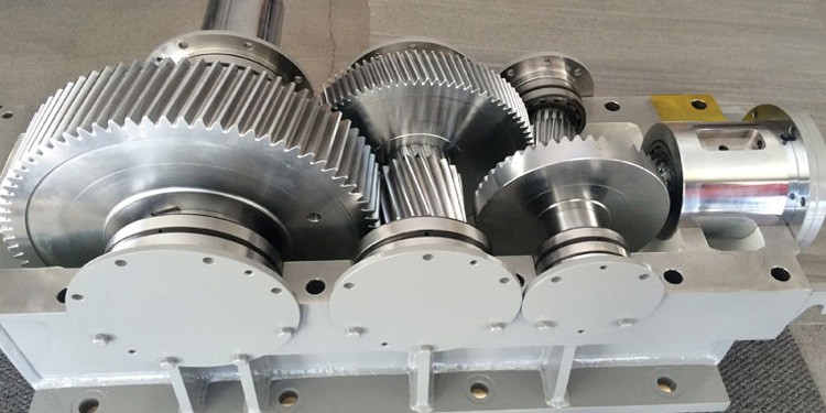
First, let's revisit the gear shaft structure, as shown in the diagram below:
The marked areas in the diagram indicate the positions where the bearings exhibited abnormal operational states. This shaft features two helical gears. Crucially, these two helical gears have opposite helix angles, and their diameters are similar.
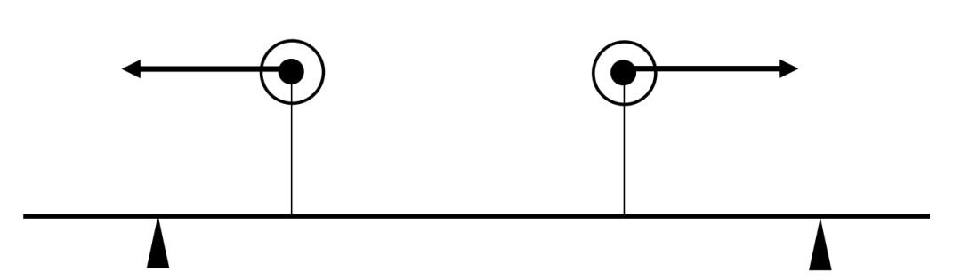
This observation is actually incredibly important for our subsequent deductions. We can roughly sketch a force diagram for this shaft:
The diagram illustrates only the forces at the two gear mesh points. Assuming the gear shaft in the photo is the driven gear and rotates clockwise when viewed from left to right, the gear mesh forces are roughly as depicted above. (It's worth noting that the gear shaft could be the driving gear or rotate in the opposite direction; however, the symmetry of the forces remains unchanged in these scenarios, which readers can analyze for themselves).
From the diagram, you can see that at the two gear mesh points, there's a circumferential load acting outward from the plane of the paper. Simultaneously, each gear experiences an outward axial load.
The circumferential load at the gear mesh, when viewed from top to bottom, translates into a radial load on the shaft system.
Therefore, this shaft system is subjected to both axial and radial forces from the meshing of the two gears. Let's set aside the radial forces for a moment and focus on the axial forces.
It's clear from the diagram that the two gears have similar tooth counts and pitch diameters. This tells us that the meshing forces of the two gears should be quite similar in magnitude. In other words, a significant portion of the axial forces generated by the meshing of these two gears in this shaft system should largely cancel each other out and, ideally, not be transmitted to the bearings.
Through the analysis above, we've concluded that the expected state of forces on this bearing system should involve a relatively large radial load and a relatively small axial load applied to the shaft system supported by the two bearings.
So, our analysis of the entire shaft system's forces provides a conclusion about what the ideal force state should be. Now, let's compare that to the actual situation with the bearings.
According to the engineer's feedback, the "disengagement" phenomenon occurred on the inner side of both bearings. The engineer did send me a video of this, but unfortunately, due to technical limitations, I can't display it here.
As we discussed in the previous article, for a spherical roller bearing to experience disengagement, there must be a relatively large axial load acting on it. And, critically, the engineer observed this disengagement on the inner side of both bearings. This implies that both bearings were subjected to significant axial loads. This type of force state is not what we predicted based on our earlier analysis of the "expected" forces. Therefore, a fault must exist, and we need to find its cause.
The next step in our analysis is to examine the bearing arrangement structure of this shaft. We need to look for any design elements or assembly issues that could lead to these unexpectedly large axial loads. Identifying these will allow us to devise a comprehensive solution to eliminate the fault. What structural details might cause such an imbalance? That's what we'll explore next!
Please contact us at https://tfl-bearing.com/contact contact for any questions about bearings, and if you are choosing a ball bearing distributor, we would be happy to give you a quote.